
Important:
Use these instructions along with the tool, parts page or manual.
Assembly:
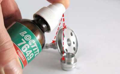
Step 1
Apply Loctite #7649 Primer or equivalent to threads on
53581 Turbine Cover and 53584 Collet Guard.
▲ Top of PageImportant:
Provide good ventilation and allow solvent to evaporate until surfaces are completely dry.
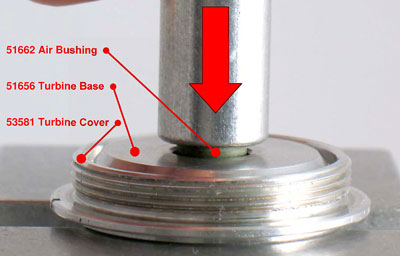
Step 2
Press new 51662 Air Bushing into 53581 Turbine Cover.
▲ Top of PageImportant:
Allow 1/16" (~1.5 mm) of bushing to jut out of turbine cover. Use 51656 Turbine Base as "JIG" to preset air bushing depth. Set aside turbine cover until STEP #13.
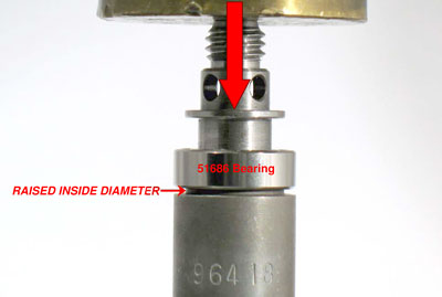
Step 3
Use "RAISED INSIDE DIAMETER" of 96418 Bearing Press Tool,
and 96232 Arbor Press to install 51686 Bearing onto
drive shaft.
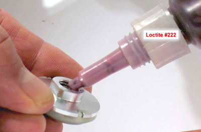
Step 4
Assemble turbine base, turbine and top plate to make the motor unit. Holding motor unit together, apply a small amount of
Loctite #222, or equivalent on threads of 51655 Top Plate. Carefully, fasten motor unit onto 53580 Drive Shaft.
Step 5
Insert 51694 Pin Wrench through cross-hole in drive shaft. Fasten in vise with aluminum or bronze jaws. Use 96408 Top Plate Wrench and torque wrench to tighten top plate.
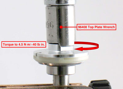
▲ Top of PageImportant:
Torque to 4.5 N·m/~40 lb in.
Step 6
Apply a small amount of Loctite #609, or equivalent to outside diameter of 51686 Bearing. Install 51661 Wave Spring and drive shaft assembly into housing.

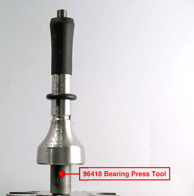
Step 7
Place “RAISED INSIDE DIAMETER” of 96418 Bearing Press Tool on table of 96232 Arbor Press. Place top plate of motor unit on “RAISED OUTSIDE DIAMETER” of 96418 Bearing Press Tool, with threaded end of drive shaft pointing up.
Step 8
Apply a small amount of Loctite #609, or equivalent to outside diameter of 51685 Bearing. Use “RAISED OUTSIDE DIAMETER” 96419 Bearing Press Tool and arbor press to install
51685 Bearing. Apply a slight load on bearings with arbor press. Check fit and rotation of bearings.
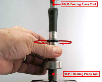
Important: Once bearing is installed, invert 96419 Bearing Press Tool with “RAISED INSIDE DIAMETER” toward inside race of 51685 Bearing.
▲ Top of PageImportant: Use a pipe-cleaner to wipe Loctite from
housing threads.
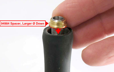
Step 9
Insert 51694 Pin Wrench through cross-holes in housing and drive shaft. Remove assembly from arbor press and fasten in vise, with threaded end of drive shaft pointing up. Install 94984 Spacer, with its larger diameter toward 51685 Bearing.
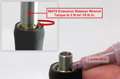
Step 10
Apply a small amount of Loctite #222, or equivalent just above 94984 Spacer. Use torque driver and 96479 Extension Retainer Wrench to install 51548 Bearing Retainer.
Torque to 2 N·m/~18 lb in.
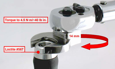
Step 11
Apply a small amount of Loctite #567, or equivalent to threads 53584 Collet Guard. Use a 14 mm crow-foot and torque wrench to install collet guard onto housing.
Torque to 4.5 N·m/~40 lb in.
Step 12
Install collet insert. Use 95731 Wrench (8 mm) to install 51657 Collet Cap. Remove pencil grinder from vise and remove 51694 Pin Wrench.
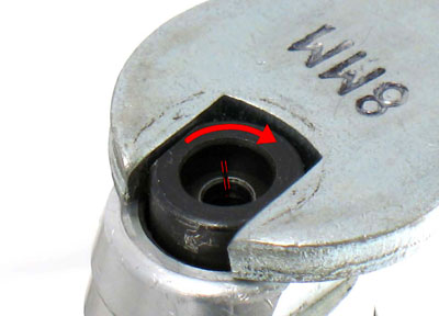
▲ Top of PageImportant:
Do not over tighten collet assembly.
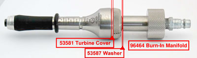
Step 13
Turbine Cover, ON/OFF Valve
and 96464 Burn-In Manifold Assembly:
a) Install 95523 O-Ring around stem of 53581 Turbine Cover.
b) Install 95438 O-Ring into 53582 ON/OFF Valve.
c) Install ON/OFF Valve onto turbine cover and turn valve to
the ON position.
d) Install 95523 O-Ring into ON/OFF Valve.
e) Install 53587 Washer onto ON/OFF Valve.
f) By hand, thread 96464 Burn-In Manifold onto turbine cover.
g) Install “Turbine Cover, ON/OFF Valve, and Burn-In Manifold Assembly” onto pencil grinder housing assembly. Tighten both assemblies all the way together by hand.
Important:
Drive shaft will not turn.
h) Connect Burn-In Manifold to air supply.
i) Slowly, loosen turbine cover until drive shaft starts to rotate
Important:
DO NOT TOUCH ROTATING COLLET-END
OF DRIVE SHAFT!
j) Continue to slowly loosen and tighten assemblies until maximum RPM is attained.
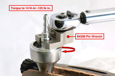
k) Use 94598 Pin Wrench to tighten assemblies.
Important:
Use a Tachometer to verify maximum RPM.

Step 14
Final Assembly:
a) Disconnect 96464 Burn-In Manifold from air supply.
b) Insert 51694 Pin Wrench through cross-hole in housing and drive shaft.
c) Fasten assembly in vise with burn-in manifold pointing up.
d) Remove turbine cover, ON/OFF valve and burn-in manifold.
e) Remove 53587 Washer from ON/OFF Valve.
f) Remove 53582 ON/OFF Valve.
g) Remove 95523 O-Ring from turbine cover.
h) Apply a small amount of Loctite #567, or equivalent to threads of turbine cover.
i) Install turbine cover onto housing.
j) Use 94598 Pin Wrench and torque wrench to tighten turbine cover.
k) Torque to 14 N·m/~125 lb in.
Step 14a
Important:
Apply oil to all three o-rings.
a) Install 95523 O-Ring around stem of 53581 Turbine Cover.
b) Install 53588 Muffler and 95438 O-Ring into
53582 ON/OFF Valve.
c) Install ON/OFF Valve onto turbine cover.
d) Install 95523 O-Ring into ON/OFF Valve.
e) Install 53587 Washer onto ON/OFF Valve.
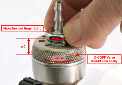
f) Apply a small amount of Loctite #609, or equivalent to turbine cover threads for 53586 Hex Nut.
g) Install hex nut finger tight. Turn clockwise.
Important: Hex nut must stay fixed. ON/OFF Valve should turn easily without any up and down movement.
g) Install hose to press firmly against 53586 Hex Nut.
Important: Allow Loctite Threadlockers and Retaining Compounds to cure/fixture for 30 minutes before checking RPM. Supply 90 psig. (6.2 Bar) maximum operating air pressure at air inlet of tool. Use tachometer to check maximum operating speed without an accessory in collet.