Drive/Motor Assembly:
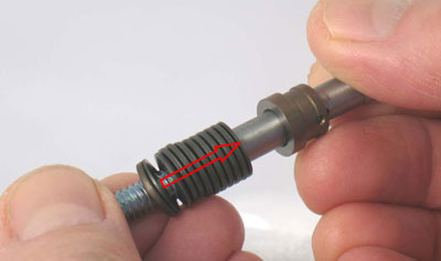
Step 1
Install 60102 Spring and 51651 Bearing
onto 60117 Drive Shaft.
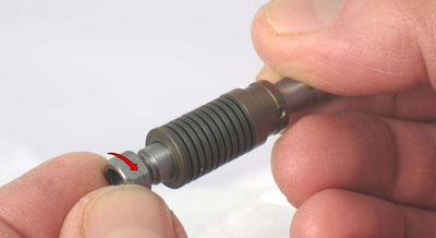
Install 60079 Screw in alignment with slot in drive shaft.
Install 60091 Pin.
Make ends of pin even with O.D. of 60078 Spring Washer.
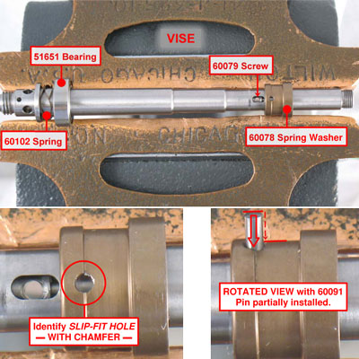
Important:Identify SLIP-FIT HOLE in 60078 Spring Washer. With larger diameter toward collet body end of drive shaft install spring washer with SLIP-FIT HOLE up. (It is helpful to rest assembly on bronze or aluminum jaws, with vise partially open.)
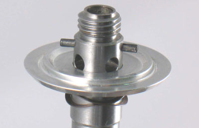
Step 2
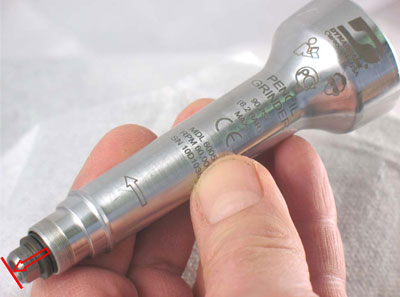
Fasten drive shaft in vise with 'Motor End' pointing up.
Install 51656 Turbine Base onto drive shaft.
Install 60098 Pin through 'Cross-Hole' so that it is 'Centered'
in drive shaft.
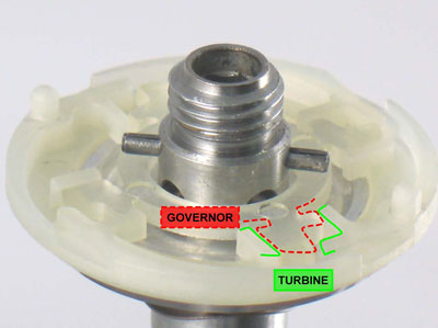
Step 3
Install 51678 Turbine and 51675 or 51691 Governor
(stretch governor around pin).
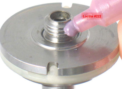
Step 4
Install 60069 Brake Plate.
Align, 'slot & notch' brake plate features, with 60089 Pin,
and 51678 Turbine.
Apply a small amount of Loctite #222 or equivalent to threads
on drive shaft.
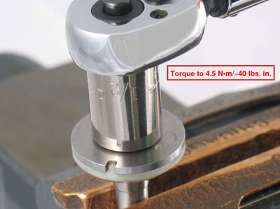
Step 5
Use 1/2" hex socket and torque wrench to install 60099 Nut.
Torque to 4.5 N•m/~40 lbs. in.
Step 6
Carefully transfer 60073 Springs, and 60074 End Support
onto drive shaft.
Step 7
Use 60077 Bumper to temporarily retain parts.
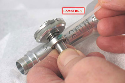
Step 8
Apply a small amount of Loctite #609 to outside diameter
of 51651 Bearing.
Step 9
Install assembly.
Step 10
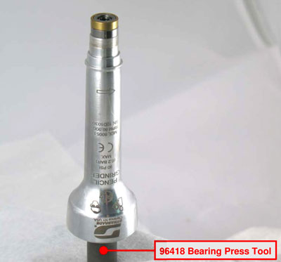
Remove 60077 Bumper. Back-Up 60099 Nut with
96418 Bearing Press Tool.
Install 60093 Bearing, 60092 Rear Seal, 60090 Inner Race Seal, 60089 Outer Housing Seal and 60088 Front Seal.
Reinstall 60077 Bumper.
Important: Push against bumper to compress spring washers while turning bumper to catch threads and
retain parts.
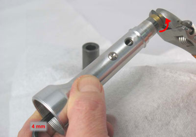
Step 11
Use a 4 mm hex key and, an adjustable wrench to fasten
60077 bumper.
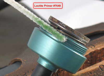
Step 12
Apply Loctite Primer #7649 or equivalent to threads of
60110 or 60111 Cover.
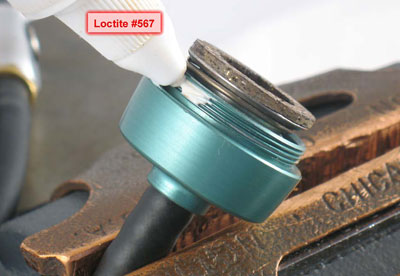
Step 13
Wait five minutes, and then apply a small amount of
Loctite #567 or equivalent.
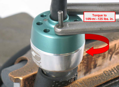
Step 14
Fasten turbine cover on housing.
Torque to 14N•m/~125 lbs. in.
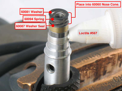
Step 15
Install 60081 Washer, 60094 Spring, and 60087 Washer Seal into 60060 Nose Cone.
Apply a small amount of Loctite #567 or equivalent to threads
on housing.
Step 16
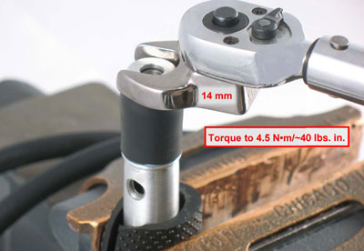
Install 60066 Nose Cone.
Use a 14 mm crowfoot and torque wrench to fasten.
Torque to 4.5 N•m/~40 lbs. in.
Step 17
Insert 60082 Cam through 60080 Cam Support.
Apply a small amount of Loctite #271 to threads of cam support.
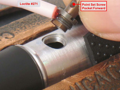
Important:
Point 'SET SCREW POCKET' forward.
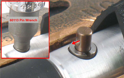
Step 18
Use 60113 Pin Wrench to fasten 60080 Cam Support
Step 19
Apply a small amount of Loctite #271 to 60112 Set Screw
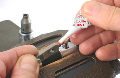
Step 20
Use 2 mm hex key to tighten 60112 Set Screw.
Fasten 60083 Lever in line with housing.
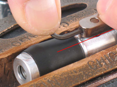
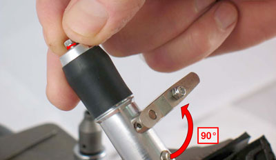
Step 21
Rotate 60083 Lever 90° to compress spring washers
and open collet.
Install 60118 or 60119 Collet Insert in drive shaft collet body.
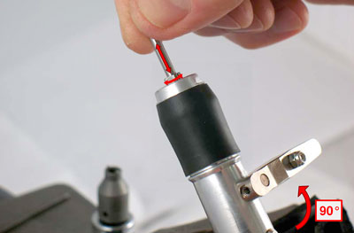
Step 22
Use 94600 (1/8") or 94601 (3/32") Ø Pin to guage correct adjustment and fit of collet inserts with 60083 Lever turned 90° to housing, insert guage pin. Check fit by inserting and removing pin. The pin should slide in and out of collet without resistance while still having a close fit.
a. If too tight, loosen collet insert slightly.
b. If too loose, tighten collet insert slightly.
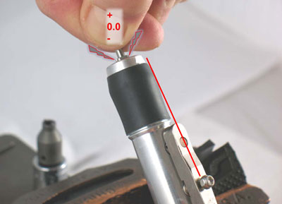
Step 23
With collet fit adjusted.
Rotate 60083 Lever into alignment with housing.
Collet will close tight on guage pin.
Drive/Motor Assembly Complete
Use tool parts page or manual to identify valve, brake and exhaust components and the order of assembly.
Important:
Allow Loctite Threadlockers and Retaining Compounds to cure/fixture for 30 minutes before checking RPM.
Fasten 94600 (1/8") or 94601 (3/32") Ø Guage Pin
into collet.
Supply 90 psig. (6.2 Bar) maximum operating air pressure at air hose of tool.
Use tachometer to check maximum speed.