Important:
Use these instructions along with the tool, parts page or manual.
Notice:
- Shut off air supply.
- Open 51655 ON/OFF Valve to deplete air.
- Disconnect tool from air supply hose.
Drive/Motor Disassembly:
Step 1
Rotate 60083 Lever 90° to open collet.
Remove insert tool from collet.
Turn counterclockwise.
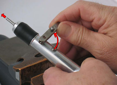
Important:
If necessary, use 60116 wrench
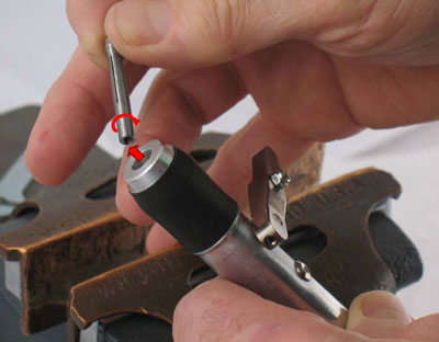
Step 2
Remove collet insert from drive shaft.
Turn conterclockwise.
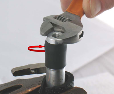
Step 3
Use a piece of rubber to protect housing and fasten in vise
with aluminum or bronze jaws.
Use an adjustable wrench to remove 60066 Nose Cone.
Turn counterclockwise.
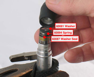
Step 4
Carefully, remove 60081 Washer, 60094 Spring and
60087 Washer Seal.
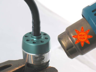
Step 5
Invert tool in vise.
Use a HEAT GUN to warm housing and soften thread sealant.
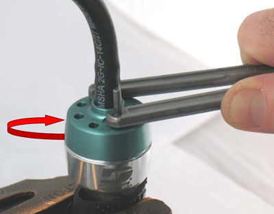
Step 6
Use an adjustable pin spanner wrench to remove
60110 or 60111 Cover.
Turn counterclockwise.
Set cover, brake and hose assemblies aside.
Important: To replace air bushing and/or brake see Disassembly/Assembly Instructions - Quick-Change Pencil Grinder, Bushing & Brake.
Step 7
Remove from vise.
Use an adjustable wrench on 60077 Bumper, and insert 4 mm hex key into end of drive shaft. Carefully, turn bumper counterclockwise to remove from drive shaft.
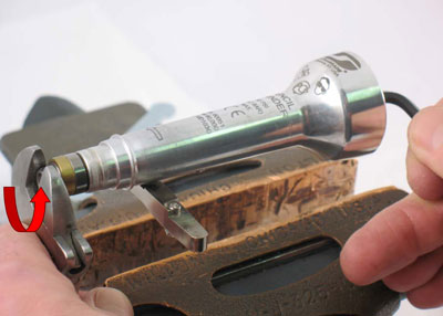
Important: Quick-Change Chuck is SPRING LOADED!
Use caution when removing 60077 Bumper.
Step 8
Use a 1/4" (6 mm) Ø diameter by ~5" (~127 mm) long screw and carefully slide, 60088 Front Seal Washer, 60089 Outer Housing Seal, 60090 Inner Race Seal, 60092 Rear Seal Washer, 60093 Bearing, 60074 End Support and 60073 Springs (19 to 20) onto screw.
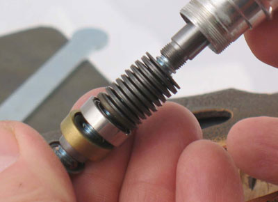
Important: Relaxed Measurement Range,
14.79 mm - 15.56 mm (~.582" - ~.613")
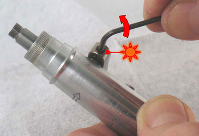
Step 9
Use a HEAT GUN to warm lever and soften Loctite #271.
Use 2 mm hex key to remove 60112 Set Screw.
Turn counterclockwise.
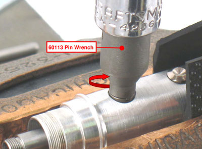
Step 10
Fasten in vise and use 60113 Pin Wrench to remove
60080 Cam Support.
Turn counterclockwise.
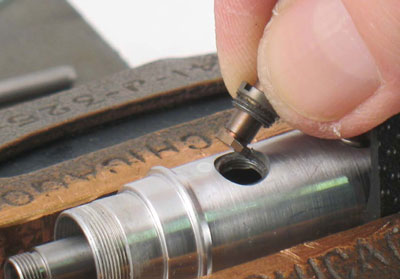
Step 11
Remove 60080 Cam Support and 60082 Cam.
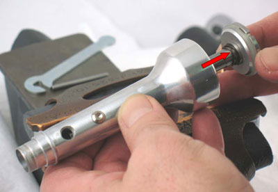
Step 12
Remove drive shaft, turbine motor, 51651 Bearing and
60102 Spring from housing.
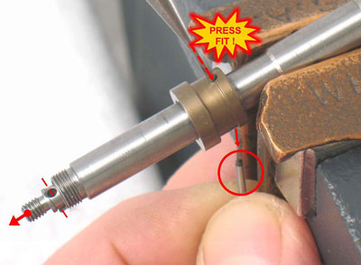
Step 13
Fasten drive shaft in vise.
Identify PRESS-FIT hole in 60078 Spring Washer.
(NO CHAMFER)
Use ~1/16" or ~1.5 mm Ø drive punch to remove the 60091 Pin.
Remove 60078 Spring Washer and 60079 Screw.
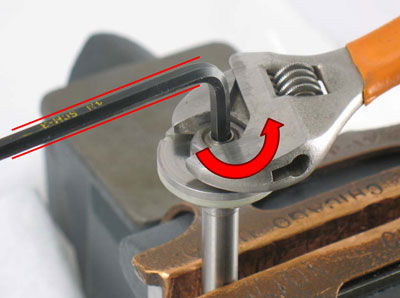
Step 14
Reposition drive shaft in vise and use 4 mm hex key
to hold it stationary.
Use an adjustable wrench to remove 60099 Nut.
Turn counterclockwise.
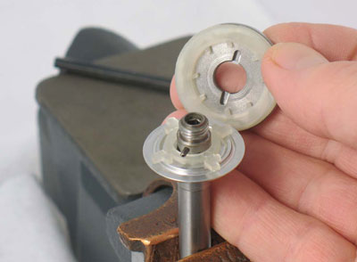
Step 15
Remove 60069 Top Brake Plate and 51378 Turbine.
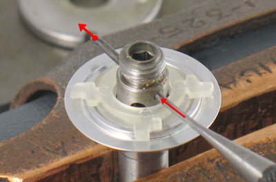
Step 16
Use ~1/16" or ~1.5 mm Ø drive punch to remove the 60098 Pin.
Remove 51675 or 51691 Governor and 51656 Turbine Base.
Disassembly Complete
Clean, inspect, and replace worn parts before assembling.