Assembly:
Step 1
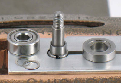
Install 55397 Spacer and 55396 Front Bearing Plate onto rotor.
Install same thickness shims, or use new .002" (0.05 mm) shim from 55414 Shim Pack. Install 55395 Bearing onto rotor.
Step 2
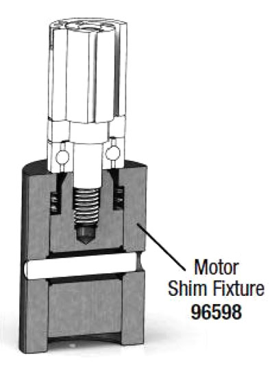
Use 96598 Motor Shim Fixture.
Thread rotor into Motor Shim Fixture, finger tight.
Install 55400 Cylinder over rotor.
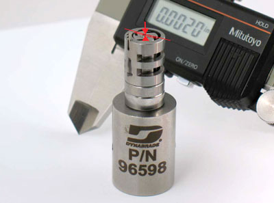
Use depth micrometer to measure distance between surface
of cylinder and surface of rotor.
Rotor should sit .0015" to .0025" (~0.04 - 0.06 mm) below cylinder. If distance needs adjustment, repeat steps, add or remove shims as required. Remove cylinder and loosen assembly from Motor Shim Fixture.
Step 3
After properly shimming, place 55398 Rotor with 55397 Spacer,
55396 Front Bearing
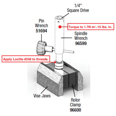
Plate, shims and 55395 Bearing into 96600 Rotor Clamp.
Tighten Rotor Clamp in vise.
Apply Loctite #248 to rotor threads and install 55392 Spindle.
Place 96599 Spindle Wrench over spindle and insert 51694 Pin Wrench.
Use 1/4" drive, torque wrench to tighten spindle.
Torque to 1.7N·m/~15 lbs. in.
Step 4
Install 55400 Cylinder with 96593 Pin, and air inlet, lined-up with holes in 55401 Rear Plate.
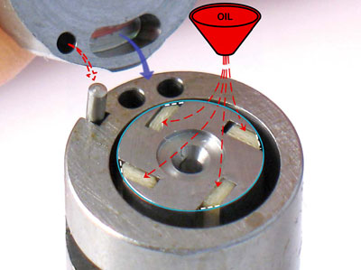
Important:
Oil 55404 Vanes. Use 95842 Dynabrade Air Lube, or equivalent. Install beveled-edge of vane to fit outside diameter of rotor.
Step 5
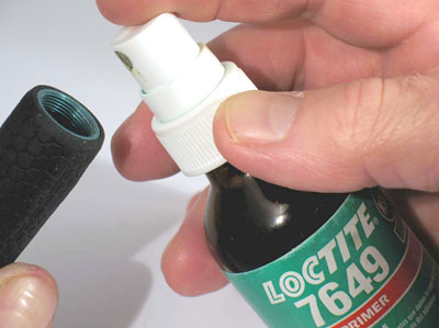
Use Loctite #7649 Primer on theads at front and rear of housing.
Also prime bearing diameter on the inside of housing.
Step 6
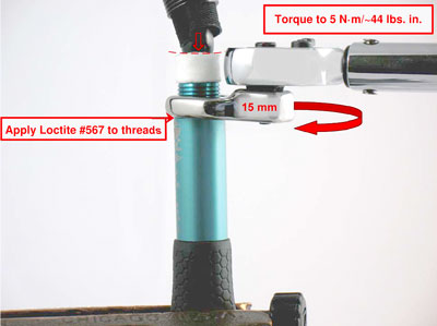
Install motor assembly along with 55402 Valve Seat, 55418 Muffler and 55419 Manifold Stem into housing. Insert 51694 Pin Wrench through housing and spindle. Fasten housing in vise with aluminum or bronze jaws, with 55419 Manifold Stem pointing up. Apply Loctite #567 to threads of 55405 Valve Lock. Use a 15 mm crowfoot wrench to fasten valve lock onto housing. Turn clockwise. Torque to 5 N·m/~44 lbs. in. Install second 55418 Muffler onto manifold stem. Install air hose with overhose and overhose clamp onto barbed end of manifold stem.
Important:
Push air hose against 55418 Muffler to compress slightly.
Step 7
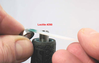
Remove housing from vise. Carefully, invert tool assembly and fasten in vise with spindle pointing up. Install 55394 Wave Spring and 55416 Spacer. Apply a small amount of Loctite #290 to the outside diameter of 51544 Bearing. Install 51544 Bearing.
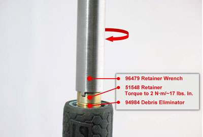
Step 8
Install 94984 Debris Eliminator with lager diameter
against bearing. Use 96479 Retainer Wrench to install
51548 Retainer. Torque to 2 N·m/~17 lbs. in.
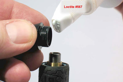
Step 9
Apply a small amount Loctite #567 to threads of
55390 Collet Guard.
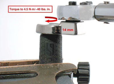
Step 10
Use a 14 mm crowfoot and torque wrench to install collet guard. Torque to 4.5 N·m/~40 lbs. in.
Step 11
Install collet insert and 51657 Collet Cap.
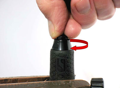
Important:
Do not over tighten collet.
Use tool parts page or manual to identify valve parts and order
of assembly.
Important:
Before checking RPM, allow Loctite Threadlockers and Retaining Compounds to cure/fixture for 30 minutes. Supply 90 psig. (6.2 Bar) maximum operating air pressure at air inlet of tool. Use tachometer to check maximum operating speed without an accessory in collet.