Important:
Use these instructions along with the tool, parts page or manual.
Notice: To avoid damage to the motor housing, use the Special Repair Tools designed for the disassembly and assembly of this motor. Disconnect the tool from the air supply. Use the appropriate wrenches to hold the work spindle stationary and remove the accessory.
Assembly
Right-Angle Head:
Step 1
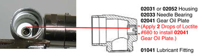
Notice: The 02033 Needle Bearing rarely requires replacement. Only remove the 02033 Bearing, and the 02041 Gear Oil Plate when the bearing needs
to be replaced.
Step 2
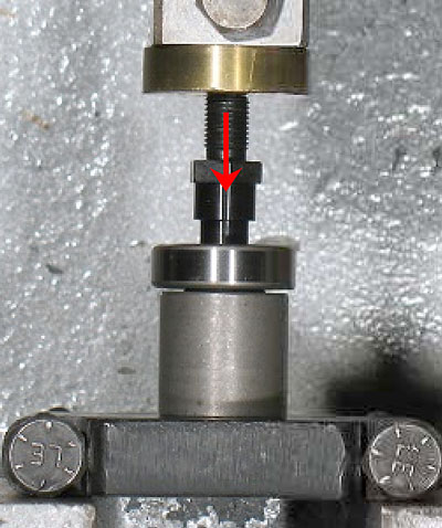
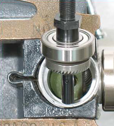
Use the Raised Center of the 96239 Bearing Press Tool and the arbor press to install the 54520 Bearing onto the work spindle.
Step 3
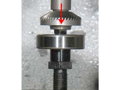
Carefully line-up the hex shaped profile in the gear and on the work spindle. Use the Raised Center of the 96419 Bearing Press Tool and the arbor press to install the bevel gear onto the work spindle.
Step 4
Saturate the lubricant wicks with the 95848 Gear Oil. Install the 02043 or 02045 Top Wick into
the right angle housing.
Place the flat side toward the pinion gear.
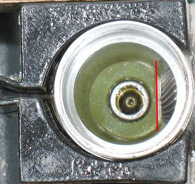
Install the 02042 or 02044 Bottom Wick.
Step 5
Install the work spindle, gear and bearing.
Step 6
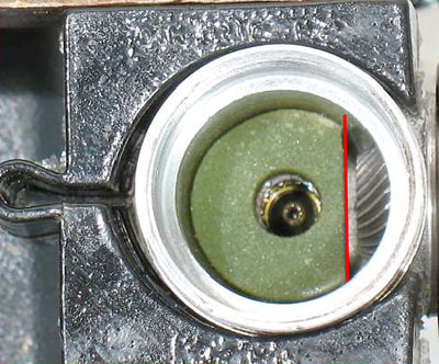
Check the rotation of the work spindle. Rotate work spindle a full 360°. Turn spindle clockwise and counterclockwise.
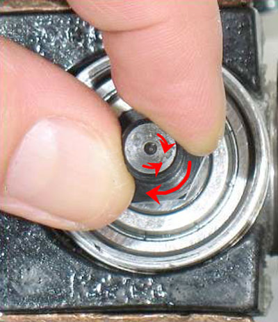
Notice: Rotation should be smooth. The backlash (clearance) between the gear teeth should be close, without being too tight.
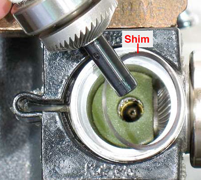
Step 7
By hand, install the 02035 Lock Nut, and check the fit of the gears. If too tight, remove the work spindle, bearing and bevel gear. As required, add or remove shim(s) to establish the correct gear fit. Install the 01486 Fabric Washer.
Step 8
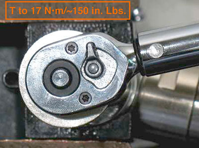
Once the gear adjustment is made, apply a small amount of the Loctite #567 to the threads of the 02035 Lock Nut.
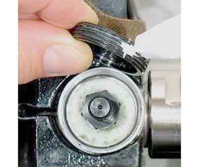
Install the lock nut and tighten. (T to 17 N•m/~150 in. Lbs.)
Step 9
Tighten the 45305 or 45307 Housing Core, or the 50019 Lock Nut onto the 02031 or 02052 Right Angle Housing.
Tool below shown has NO Planetary Gear Set.
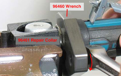
Tool below shown has a Planetary Gear Set.
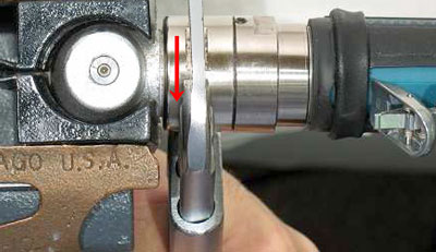
Notice: For both Planetary and Non-Planetary Geared tools work the left hand thread and right hand thread against each other while holding the throttle lever in the desire position. (T to 34 N•m/~300 in. Lbs.)
Step 10
Move 01547 Insulating Collar back into the proper position.