Assembly:
Step 1
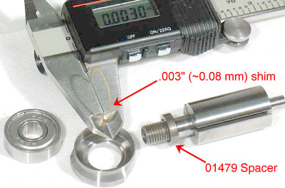
Install the 01479 Spacer onto the rotor.
Step 2
Select .003" (~0.08 mm) shim thickness from the 54529 Shim Pack. Install shims in the 01478 Front Bearing Plate.
Step 3
Install the 02649 Bearing into the front bearing plate and
onto the rotor.
Notice: Planetary geared models use the Raised Center of the 96240 Bearing Press Tool and the arbor press to install the 02649 Bearing with the bearing plate onto
the rotor.
Step 4
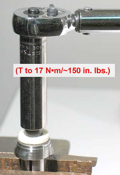
Fasten the rotor in the vise with aluminum or bronze jaws so that the spindle is pointing up. Use a 12 mm socket and torque wrench to install the 01435 Collet Body (T to 17 N•m/~150 in. lbs.)
Step 5
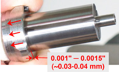
Pull the front bearing plate forward to take play out of the bearing. Use a .001" (~0.03 mm) thick feeler gauge to check the clearance between the bearing plate and rotor.
Step 6
Clearance should be .001"-.0015" (~0.03-0.04 mm).
Notice: Repeat steps 2-5 If clearance needs further adjustment. Install or remove shims as required.
Step 7
Use Dynabrade Air Lube 95842 10W/NR (or equivalent) to lubricate the 01480 Vanes. Install the vanes in the rotor.
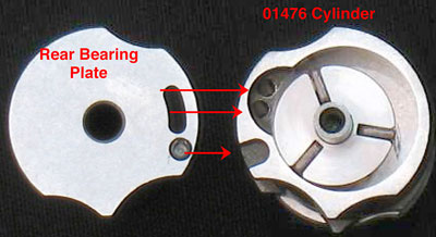
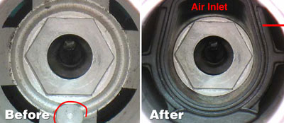
Step 8
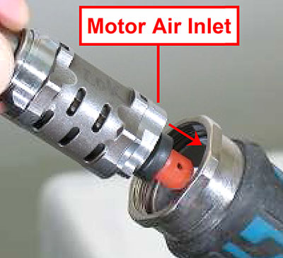
Install the 01476 Cylinder and the 02676 Rear Bearing Plate
so that the air inlet openings line-up.
Step 9
Position the 02696 Bearing onto the bearing journal of the rotor.
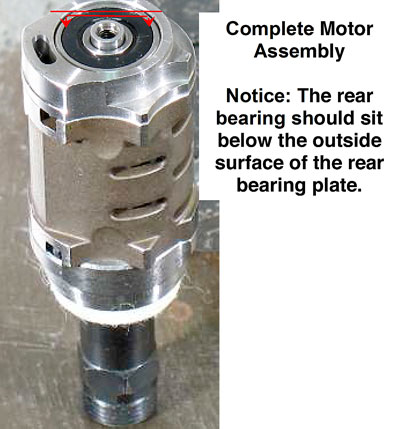
Step 10
Use the Raised Center of the 96242 Bearing Press Tool and the arbor press to install the 02696 Bearing onto the rotor, and into the 02676 Rear Bearing Plate.
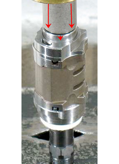
Important: Carefully press the bearing until the plate just touches the cylinder. This will establish a "snug-fit" between the bearing plates and the cylinder.
Step 11
Apply a small amount of Loctite #243 (or equivalent) to the threads of the governor assembly and carefully install the governor onto the rotor.
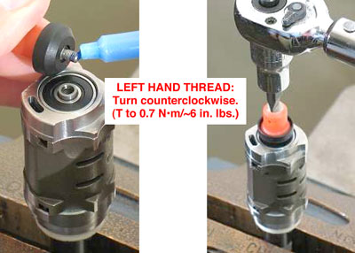
Important: Left Hand Thread - Turn counterclockwise.
(T to 0.7 N•m/~6 in. lbs.)
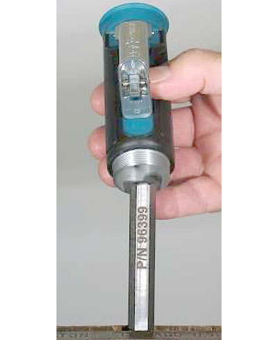
Step 12
Fasten the 96399 Hex Key (12 mm) in a vise with aluminum or bronze jaws so that it is pointing up. Place the 45305 or 45307 Housing Core onto the 12 mm hex key so pointing up.
Step 13
Refer to the parts page or tool manual and follow the exploded view instructions to assemble the muffler and valve components.
Step 14
Install the 01564 Air Control Ring onto the 01578 or 94523 Inlet Adapter and apply a small amount of Loctite #567 to the male threads of the inlet adapter.
Step 15
Use a torque wrench to install the inlet adapter.
(T to 28 N•m/~250 in. lbs.)
Step 16
Line-up the 45320 Governor Chamber pin with the hole on the inside of the 45305 or 45307 Housing Core.
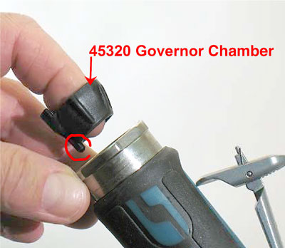
Step 17
Install the 45320 Governor Chamber.
Step 18
Carefully line-up and install the motor assembly.