Motor Assembly:
Step 1
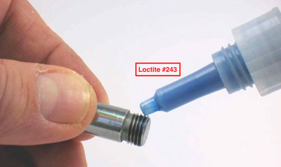
Identify the end of the 53635 Adapter without the 3/16" hex.
Apply a small amount of Loctite
#243 or equivalent to the thread on that end.
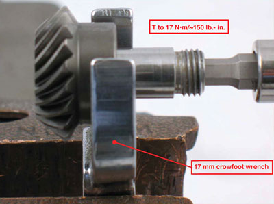
Use a 17 mm wrench, a 3/16" hex key bit and torque wrench to fasten the 53635
Adapter to the pinion gear.
(T to 17 N•m/~150 lb.- in.)
Step 2
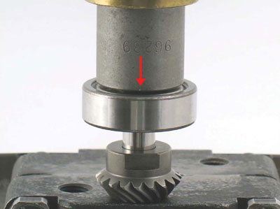
Position the pinion gear on the table of the 96232 Arbor Press (#2) with the 53635 Adapter pointing up. Use the RAISED INSIDE DIAMETER of the 96239 Bearing Press Tool to install the
01266 Bearing.
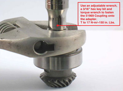
Step 3
Apply a small amount of Loctite #243 or equivalent to the thread of the adapter.
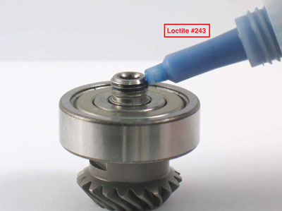
Use an adjustable wrench, a 3/16" hex key and torque wrench to install the 51969 Coupling. T to 17 N•m/~150 in. lbs.
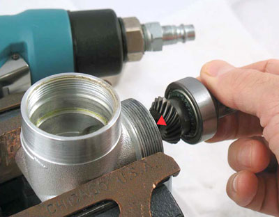
Step 4
Install the pinion gear assembly into the
53600 Right Angle Housing.
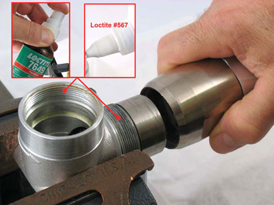
Install the longer-end of the 53651 Spacer into the 53600 Right Angle Housing. Apply Loctite Primer #7649 or equivalent to threads of the 53600 Right Angle Housing. Apply a small amount of Loctite #567 or equivalent to threads of the
right angle housing.
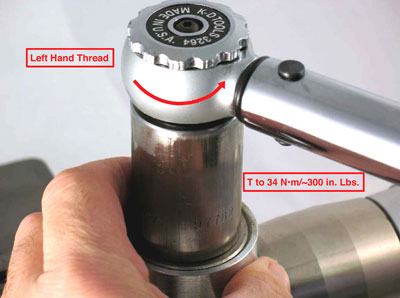
Step 5
Install the 53650 Lock Ring along with the motor assembly onto the 53600 Right Angle Housing. Left Hand Threads Turn counterclockwise. Notice: Carefully join the 51969 Couplings and 50902 Coupling Insert, using the right hand and left hand thread connections. With assemblies properly aligned, locate the throttle lever to the desired position. Use a 45 mm (~1-25/32") crowfoot to tighten the lock ring.
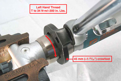
Important: Turn counterclockwise
T to 34 N•m/~300 in. Lbs.
Step 6
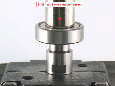
Position the spindle in and the arbor press so that the threaded end is pointing down. Use a 11/16" or 18 mm deep well socket as a press tool to install the 97679 Bearing onto the spindle.
Push it all the way down against the step.
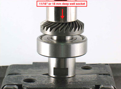
Use a 11/16" or 18 mm deep well socket as a press tool to install the bevel gear onto the spindle. Push it all the way down against the bearing.
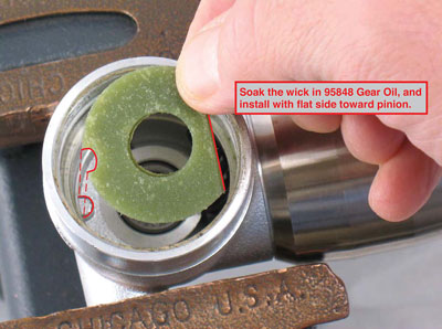
Step 7
Soak the 53608 Wick in the 95848 Gear Oil and install the wick into the right angle housing with the flat edge towards pinion gear.
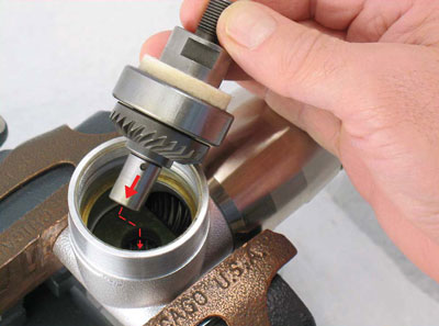
Step 8
Install the 53609 Felt Seal onto the spindle and gear assembly.
Important:
Do not install shims at this point.
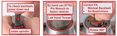
Step 9
Apply downward force on the spindle and rotate the spindle forwards and backwards to check the amount of backlash or free movement between the gear teeth. There should be a minimal amount of free movement between the teeth. By hand, use the 97782 Pin Wrench or an adjustable pin wrench to fasten the 50963
Retainer into the housing.
LEFT HAND THREAD Turn counterclockwise.
Check rotation of the spindle and gear assembly 360°. The correct fit should have
minimal backlash without any restricted movement between the gear teeth. Add or remove shims to adjust the correct gear fit (amount of backlash).
Step 10
Use the 97782 Pin Wrench and torque wrench to fasten
50963 Retainer.
Important:
Left Hand Thread, Turn counterclockwise.
(T to 34 N•m/~300 in. lbs.)
Right Angle Gear Assembly Completed
Initially, use the 95541 Lubricant Gun to apply two plunges of the 95848 Gear Oil through the 01041 Lubricant Fitting. Continue to apply two plunges of gear oil after every eight hours of use. Refer to the tool parts page or manual and follow directions for checking RPM before installing any accessories. If necessary, install guards or shrouds. Use the appropriate wrenches to hold the work spindle stationary to install accessories.