Motor Assembly:
Step 1
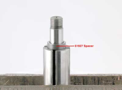
Fasten the rotor in a vise with aluminum or bronze jaws so that the work spindle is pointing up. Install the 51927 Spacer onto the rotor.
Step 2
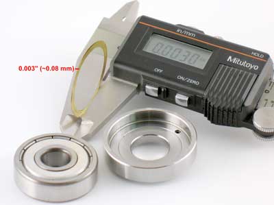
Select .003" (~0.08 mm) shim thickness from the 51951 Shim Pack. Install shims into the 51922 Front Bearing Plate.
Install the 54520 Bearing.
Step 3
Install the 51922 Front Bearing Plate and bearing onto the rotor.
By hand, install the 50011 Collet Body onto the rotor.
Use a .001" (~0.03 mm) feeler gauge to check the gap between the rotor and the front bearing plate.
The correct gap should be .001" - .0015" (~0.03 mm - ~0.04 mm).
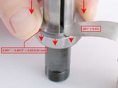
Add or remove shim thickness to set
the correct gap.
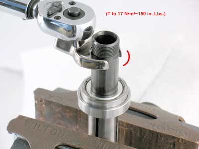
Use a 14 mm crowfoot and torque wrench to fasten the
50011 Collet Body onto the rotor. (T to 17 N•m/~150 in. Lbs.)
Step 4
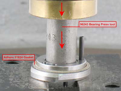
Use a mild solvent to remove all oil from the 51923 Rear Bearing Plate. Peel the backing from the 51924 Gasket and adhere the adhesive side to the bearing plate. Use the Raised Outside Diameter of the 96243 Bearing Press tool and the 96232 Arbor Press (#2) to fully install the 02057 Bearing into the 51923 Rear Bearing Plate.
Step 5
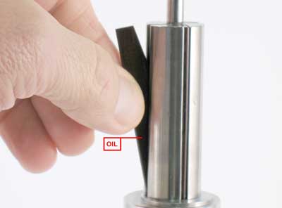
Apply the 95842 Dynabrade Air Lube or equivalent to the
51926 Vanes and install them into the rotor.
Step 6
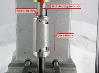
Install the 51925 Cylinder so that the air inlet opening in the 51923 Rear Bearing Plate will line-up with the air inlet in the cylinder.
Step 7
Use the RAISED INSIDE DIAMETER of the 96243 Bearing Press Tool and the arbor press to install the 02057 Bearing and rear bearing plate onto the rotor. Carefully press the bearing and plate down until the plate just touches the cylinder. This will establish a close fit between the bearing plates and the cylinder.
Step 8
Fasten the 50011 Collet Body in the vise with aluminum or bronze jaws so that the back end of the motor is pointing up.
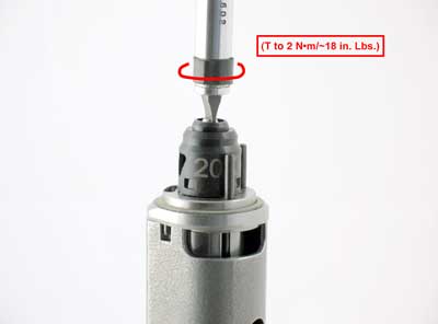
Apply a small amount of Loctite #243 to the thread
of the governor.
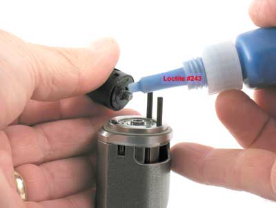
Use a torque driver to install the governor onto the rotor.
Left Hand Thread Turn counterclockwise. (T to 2 N•m/~18 in. Lbs.)
Step 9
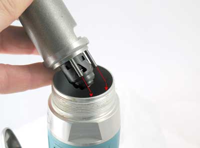
Use the 51989 Repair Collar to hold the motor housing in a vise so that the opening of the housing is pointing up. Line-up the 96445 Pins with the notches on the inside of the housing and install the motor.
Install the 53620 Motor Adapter with o-ring, and the
96498 Wave Spring. Apply Loctite
Primer #7649
or equivalent to the housing thread.

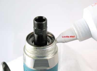
Apply a small amount of Loctite #567 to housing thread.
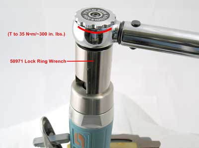
Use the 50971 Lock Ring Wrench and torque wrench to install 51947 Housing Cover. (T to 35 N•m ~300 in. lbs.)
Step 10
Install collet insert and 50012 Collet Cap.
Assembly Complete
Refer to the parts page or tool manual, and follow the exploded view instructions to disassemble and assemble the muffler and valve components.▲ Top of Page