Motor Assembly:
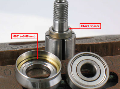
Step 1
Fasten the rotor in a vise with aluminum or bronze jaws so that the rotor spindle is pointing up. Install the 01479 Spacer onto the rotor. Install .003" (~0.08 mm) shim thickness into the 01478 Front Bearing Plate.
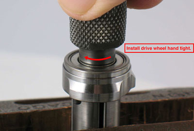
Step 2
Install the 02649 Bearing into the front bearing plate. Install the bearing and plate onto the rotor. Install the drive wheel hand tight.
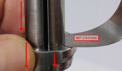
Step 3
Use a .001" (~0.3 mm) thick feeler gauge to check clearance between the front bearing plate and the front of the rotor. Push down on the bearing plate to take movement out of the bearing. The clearance should be .001"-.0015" (~0.3 - ~0.4 mm).
Notice: If the clearance needs further adjustment repeat steps 2-3. Add or remove shims as required.
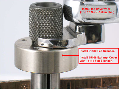
Step 4
Once the correct clearance is achieved, remove the drive wheel and install the 01580 Felt Silencer around the rotor spindle. Install the 15111 Felt Silencer into the 15106 Exhaust Cover and place these onto the rotor. Install the drive wheel.
(T to 17 N•m/~150 in. lbs.)
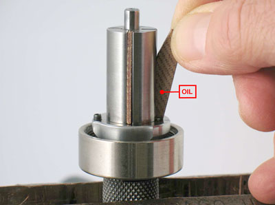
Step 5
Lubricate the 01480 Vanes with the 95842 Dynabrade Air Lube 10W/NR or equivalent. Install oiled vanes.
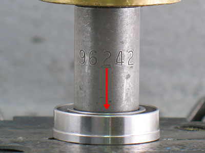
Step 6
Use the RAISED OUTSIDE DIAMETER of the 96242 Bearing Press Tool and the 94232 Arbor Press (#2) to install the
02696 Bearing into the 02673 Rear Bearing Plate.
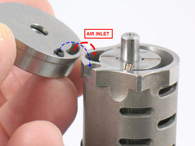
Step 7
Install the 01476 Cylinder so that the air inlet opening in the 02673 Rear Bearing Plate will line
up with the air inlet opening
of the cylinder.
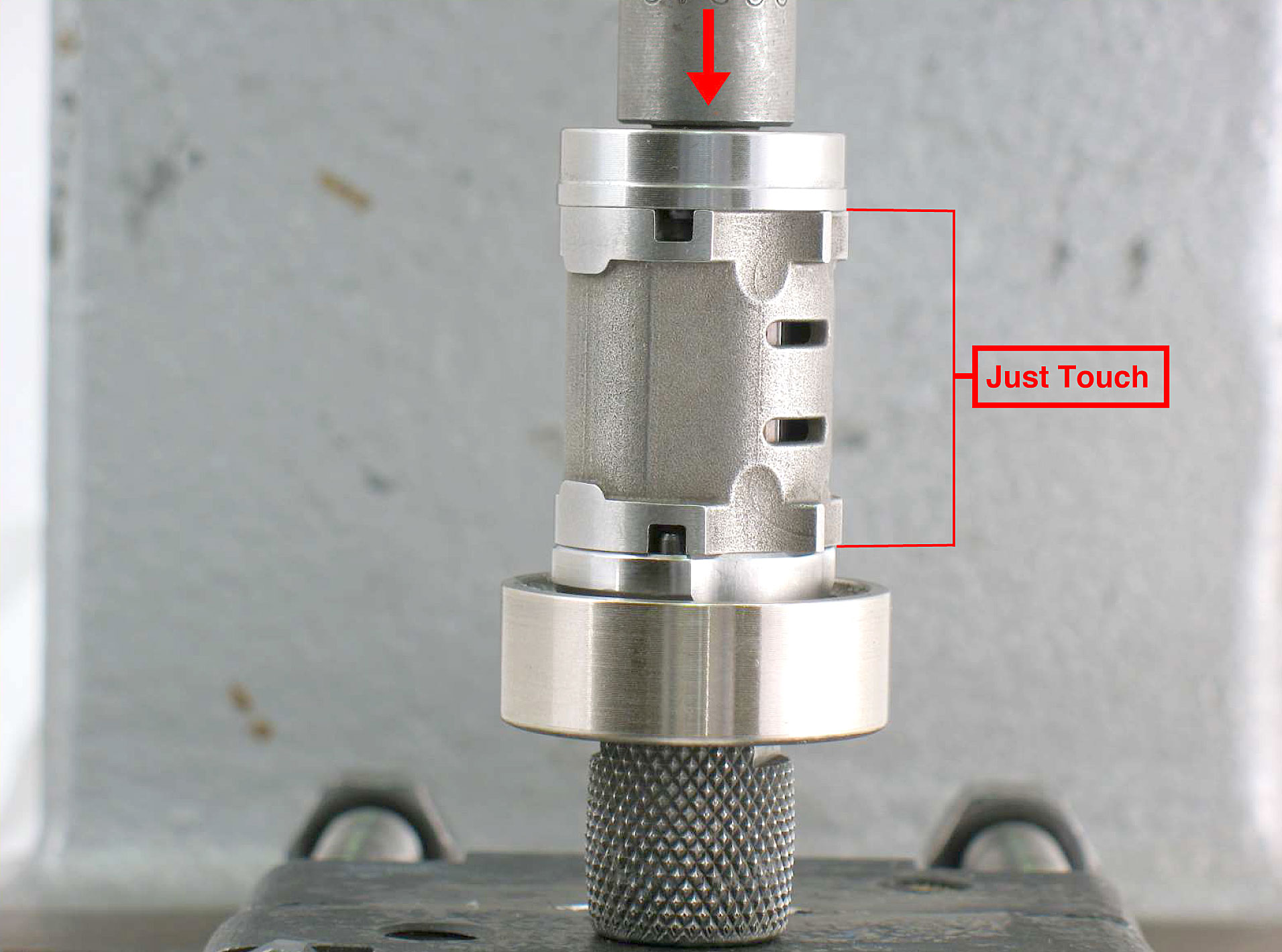
Step 8
Use the RAISED INSIDE DIAMETER of the 96242 Bearing Press Tool and the arbor press to install the rear bearing and
plate
onto the rotor.
Notice: Carefully press the bearing and plate down until it just touches the cylinder. This will establish a close fit between the bearing plates and the cylinder.
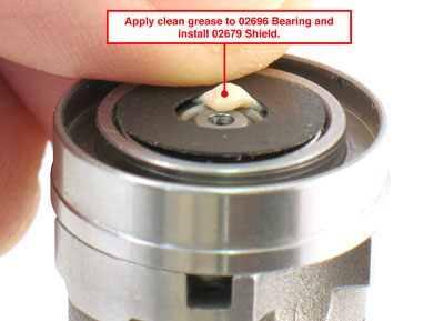
Step 9
Apply a small amount of clean grease to the seal of the
02696 Bearing. Install the 02679 Shield.
Notice: The grease is used to hold the shield against the seal of the bearing.
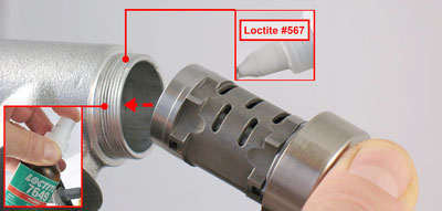
Step 10
Carefully install the motor assembly into the 01546 Housing.
Apply Loctite® #7649 Primer or equivalent to the thread of the
01546 Housing. Apply a small amount of Loctite® #567 or equivalent to the 01546 Housing
.
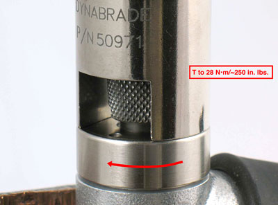
Step 11
Carefully fasten the 01546 Housing in the vise with aluminum or bronze jaws so that the drive wheel is pointing up.
Use the
50971 Lock Ring Tool and a torque wrench, or an adjustable
3 mm pin spanner wrench to fasten the 15106 Exhaust Cover onto the 01546 Housing. (T to 28
N•m/~250 in. lbs.)
Notice: Over tightening vise will damage housing.
Repair Collar 96461 (designed to protect the
01546 Housing) is available upon order.
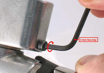
Step 12
Install air motor into the 15060 Housing Assembly. Use a 3 mm hex key to tighten the 01788 Motor Lock Screw.
Notice: For belt housing, contact arm and valve assemblies, refer to the exploded view and the additional instructions contained in the tool parts page or manual.
Motor Assembly Completed
▲ Top of Page