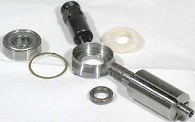
Disassembly:
Use these instructions along with the tool, parts page
or manual.
Important: To avoid damage to the motor housing, use the Special Repair Tools designed for the disassembly and assembly of this motor (see below).
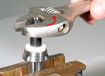
Disconnect the tool from the air supply. Use the appropriate wrenches to hold the work spindle stationary and remove the accessory.
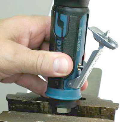
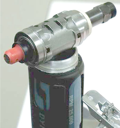
Step 1
With the tool spindle pointing up, fasten the 01578 or
94523 Inlet Adapter in a vise with aluminum or bronze jaws.
Notice: If the 01578 or 94523 Inlet Adapter loosens before the rear exhaust cover or planetary housing, remove the inlet adapter, muffler and valve parts.
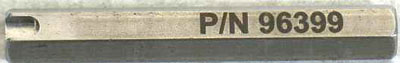
Fasten the 96399 Hex Key (12 mm) in the vise with the notched end pointing up.
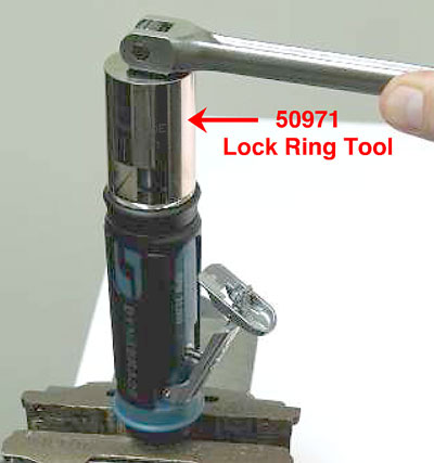
Step 2
Use the 50971 Lock Ring Tool to remove the rear exhaust cover or planetary housing. Place the air inlet of the 45305 Housing Core onto the 96399 Hex Key. Line-up notch with the 97045 Pin. Use the 50971 Lock Ring Tool to remove the rear exhaust cover or planetary housing from the 45305 Housing Core.
To disassemble the muffler and valve components, refer to, and follow the exploded view instructions found in the parts page or tool manual.
Important: Turn counterclockwise.
Notice: For angle-head models use the
97782 Lock Ring Tool to remove the planetary
adapter/gear case.
Step 3
Remove the motor from the housing.
Step 4
Carefully hold the tool spindle or pinion in the vise with aluminum or bronze jaws so that the governor is pointing up.
Step 5
Use a slot-blade screwdriver to remove the governor.
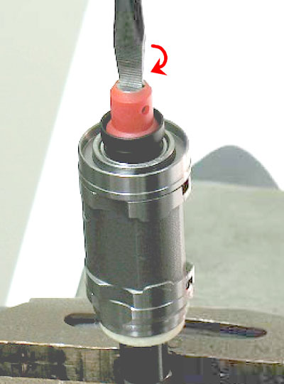
Important: Left Hand Thread - Turn clockwise.
Notice: The governor assembly is not serviceable.
If the governor fails, it must be replaced as a complete assembly. (No governor on 35,000 RPM models.)
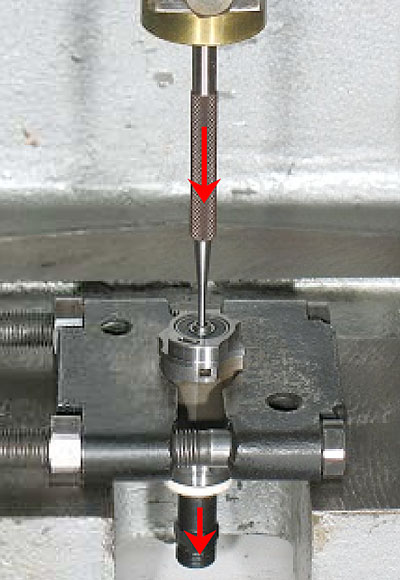
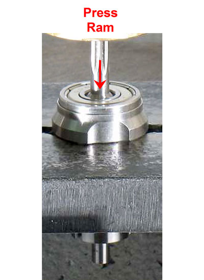
Step 6
Fasten the 96346 Bearing Separator (2") around the
01476 Cylinder. Place the bearing separator and the motor
in the 96232 Arbor Press (#2) with the tool spindle
pointing down.
Step 7
Use a 3/32" (2.38 mm) diameter flat-end drive punch as a press tool to push the rotor out of the 02696 Bearing.
Step 8
Remove the cylinder and vanes.
Step 9
By hand, use the 3/32" (2.38 mm) diameter flat-end drive
punch to push the 02696 Bearing (slip-fit) out of the
02676 Rear Bearing Plate.
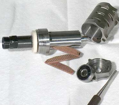
Step 10
Use a wrench to remove the 01435 Collet Body or pinion. Remove the 01478 Front Bearing Plate, 02649 Bearing,
shims, and 01479 Spacer.
Important: Turn counterclockwise.
Notice: Planetary gear models, use the arbor press to remove the front bearing and plate.
Disassembly Complete