Important:
Use these instructions along with the tool, parts page or manual.
Notice: Shut off the air supply and depress throttle lever to dissipate the remaining air. Carefully disconnect the tool from the air supply hose. Remove the abrasive belt and contact arm assembly. Use the Special Repair Tools designed for the disassembly and assembly of this motor.
Assemby of Dynafile®
Step 1
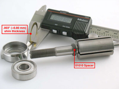
Install the 01010 Spacer onto the rotor. Install .003" (~0.80 mm) shim thickness into the 01008 Front Bearing Plate. Install the 01007 Bearing into the front bearing plate. Install the bearing
and plate onto the rotor.
Step 2
By hand, install the 04081 Rotor Nut. Pull the front bearing plate forward to take movement out of the bearing. Check the clearance between the rotor and plate. Use a .001" (~0.03 mm) thick feeler gauge.
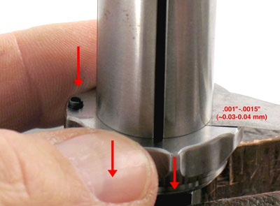
Notice: The clearance should be .001"-.0015"
(~0.03-0.04 mm). If the rotor/plate clearance needs adjustment, repeat steps 1 and 2.
Remove or add shims as required.
Step 3
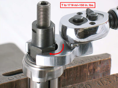
Use a 17 mm socket or crowfoot, and a torque wrench to tighten the 04081 Rotor Nut. (T to 17 N•m/~150 in. lbs.)
Step 4
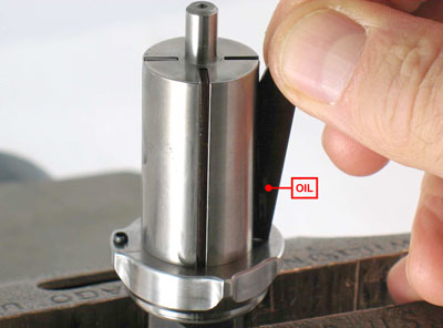
Apply the 95842 Dynabrade Air Lube, 10W/NR or equivalent
to the 01011 Vanes and install them into the rotor.
Step 5
Use the Raised Outside Diameter of the 96241 Bearing Press Tool and the arbor press to install the 01015 Bearing.
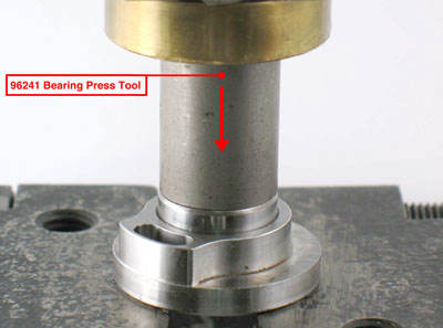
Notice: Press the bearing all the way into the plate.
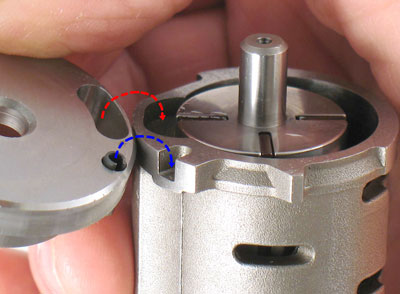
Step 6
Install the cylinder and the rear bearing plate so that the air inlet openings line-up with each other.
Step 7
Use the Raised Inside Diameter of the 96241 Bearing Press Tool and the arbor press to install the bearing and plate.
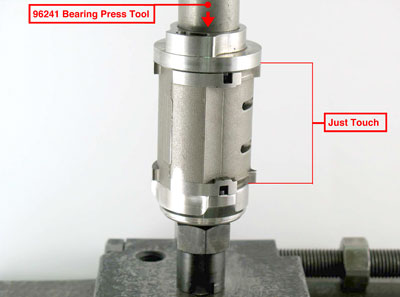
Important: Press the bearing and plate down until the rear bearing plate just touches the 01013 Cylinder. This will produce a close fit between the bearing plates and the cylinder and establish proper preload on the
motor bearings.
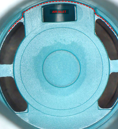
Step 8
Line-up the air inlet of the rear bearing plate with the air inlet in the housing. Install the motor assembly.
Step 9
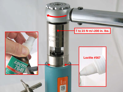
Fasten the housing flats of the 01197 Air Motor in the vise with aluminum or bronze jaws so that the rotor spindle is pointing up. Install the 04078 Felt Silencer around the 04084 Air Control Ring and install these into the 04087 Lock Ring. Apply Loctite #7649 Primer to the thread of the 04087 Lock Ring.
Apply a small amount of Loctite #567 or equivalent the 04087 Lock Ring. Use the 50971 Lock Ring Tool and a torque wrench to install the 04087 Lock Ring.
(T to 23 N·m/~200 in. lbs.)
Step 10
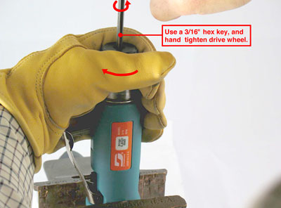
Insert a 3/16" hex key through the 01111 Drive Wheel and into the end of the 01120 Rotor to hold it stationary. By hand, install the drive wheel.
Important: Use a tachometer to check motor speed and to verify proper operation. Once the proper RPM has been verified, remove the drive wheel and install
the 10295 Screen.
Step 11
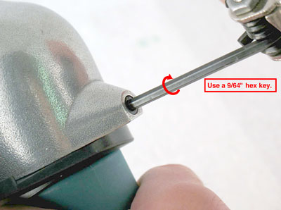
Install the 11424 Wave Spring and the 11419 Cover onto the 01197 Air Motor. Insert the 01197 Air Motor into the
11418 Housing. Use a 9/64" hex key to fasten the motor
with the 95311 Screw and 40029 Cam Lock.
Notice: For belt housing, contact arm and valve assemblies, refer to the exploded view and additional instructions that are contained in the tool parts page or manual. Click here and enter your model number for the current parts page or manual.